
Exp 8. Diode Bridge Rectifier with Filter
Concept : To demonstrate the working of a Bridge Rectifier and a RC Filter
Explanation:
A diode bridge rectifier with a filter is a common circuit used to convert alternating current (AC) to direct current (DC) with reduced ripple. Here’s a brief overview of how it works:
Components:
- Diodes: Four diodes arranged in a bridge configuration.
- Transformer: Often used to step down the AC voltage.
- Filter Capacitor: Used to smooth out the DC output.
- Load Resistor: Connected to the output to utilize the DC power.
Working Principle:
Rectification:
- During the positive half-cycle of the AC input, two diodes (D1 and D2) conduct, allowing current to pass through the load resistor in one direction.
- During the negative half-cycle, the other two diodes (D3 and D4) conduct, again allowing current to pass through the load resistor in the same direction.
- This results in a pulsating DC output.
Filtering:
- The filter capacitor is connected across the load resistor.
- It charges during the peaks of the pulsating DC and discharges when the voltage drops, thereby smoothing the output and reducing the ripple.
Simulation Mode: Transient
Simulation Parameters: .tran 0.001 0.5 0 UIC
|
Simulation Type |
Start Time(sec) |
Stop Time(sec) |
Step Time(sec) |
|
.tran |
0 |
0.5 |
0.001 |
Reference Netlist:
* Diode Bridge Rectifier with Filter
.model mydiode D
.model mydiode D
.model mydiode D
.model mydiode D
D1 0 COM.1 mydiode
D2 COM.1 COM.2 mydiode
D3 0 COM.3 mydiode
D4 COM.3 COM.2 mydiode
R1 COM.2 0 1k
V1 COM.1 COM.3 SIN(0 240 50 0.0 0.0 0.0 )
C5 COM.2 0 1m
.tran 0.001 0.5 0 UIC
.control
run
plot all
.endc
.end
Reference Circuit Schematic:
Make the circuit diagram with the exact pin-to-pin connection as shown below to practice. This will help you to complete the experiment successfully.
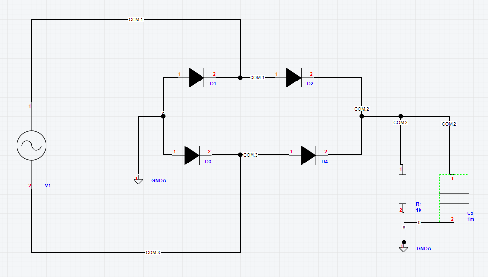
Supply Details:
Input=COM.1 and Output=COM.2
Reference Output:
After the simulation is done, the following output graph appears at the screen showing the voltages and currents across all the nodes.
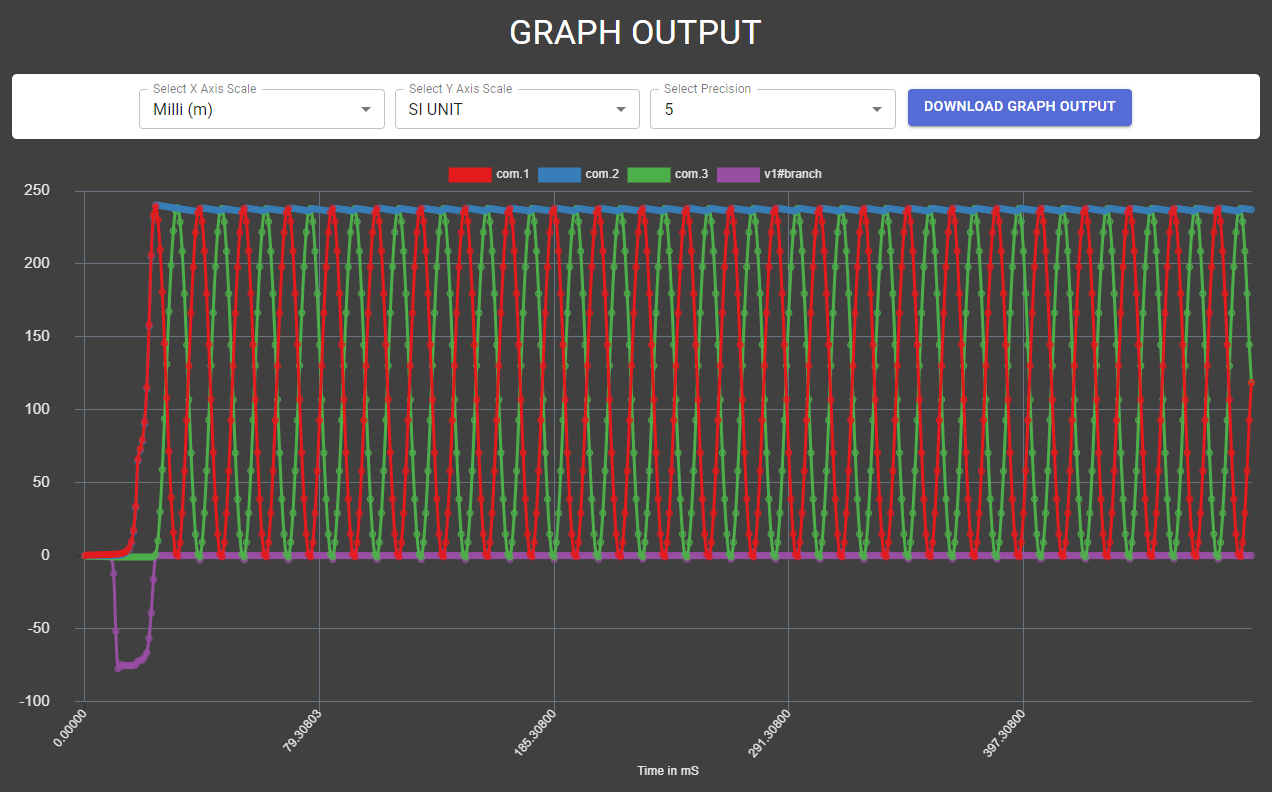
Conclusion:
The output of the bridge rectifier is filtered as shown in the output giving out an almost DC signal with ripples.
Assignment:
Add a zener regulator at the end of the above circuit and get a regulated output. Note: A zener diode spice model file may be required.
< Exp 7. Diode Bridge Rectifier up Exp 9. BJT Fixed Bias CE Amplifier >