
Exp 6. Positive Diode Clipper
Concept : To demonstrate the working of a Positive Diode Clipper
Explanation:
A diode clipper is a circuit that uses diodes to "clip" or cut off portions of an input signal without distorting the remaining part of the waveform. It effectively limits the voltage of a signal to a specific level, thereby protecting circuits from excessive voltage or shaping the waveform to meet specific requirements.
Basic Principles of Diode Clipping
-
Clipping: Clipping is the process of limiting the voltage level of a signal. When the input voltage exceeds a certain threshold, the excess voltage is "clipped" off.
-
Diodes: Diodes allow current to flow in one direction (forward-biased) and block it in the opposite direction (reverse-biased). This characteristic is used in clipper circuits to control the voltage levels.
Types of Diode Clippers
There are various types of diode clippers based on their configuration and the clipping behavior:
-
Series Diode Clipper
-
Parallel Diode Clipper
-
Biassed Diode Clipper
-
Combination Clipper
Here we are going to try out the Series Diode Negative Clipper.
In a series diode clipper, the diode is placed in series with the load. This configuration clips either the positive or negative half of the input waveform, depending on the orientation of the diode.
Positive Clipping: The diode is oriented to conduct during the positive half of the input signal.
-
When the input signal is positive and exceeds the forward voltage of the diode, the diode conducts, shunting the current and maintaining the output voltage at the diode's forward voltage (e.g., 0.7V for a silicon diode).
-
When the input signal is negative, the diode is reverse-biased, and the signal is passed through to the output.
Simulation Mode: Transient
Simulation Parameters: .tran 0.0001 0.05 0
|
Simulation Type |
Start Time(sec) |
Stop Time(sec) |
Step Time(sec) |
|
.tran |
0 |
0.05 |
0.0001 |
Reference Netlist:
* Positive Diode Clipper
.model mydiode D
V1 COM.1 0 SIN(1.0 5 1K 0.0 0.0 0.0 )
D1 COM.2 COM.1 mydiode
R1 COM.2 0 1k
.tran 0.0001 0.05 0
.control
run
plot all
.endc
.end
Reference Circuit Schematic:
Make the circuit diagram with the exact pin-to-pin connection as shown below to practice. This will help you to complete the experiment successfully.
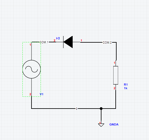
Reference Circuit Details:
Input Voltage=COM.1
Output Voltage=COM.2
Reference Output:
After the simulation is done, the following output graph appears at the screen showing the voltages and currents across all the nodes.
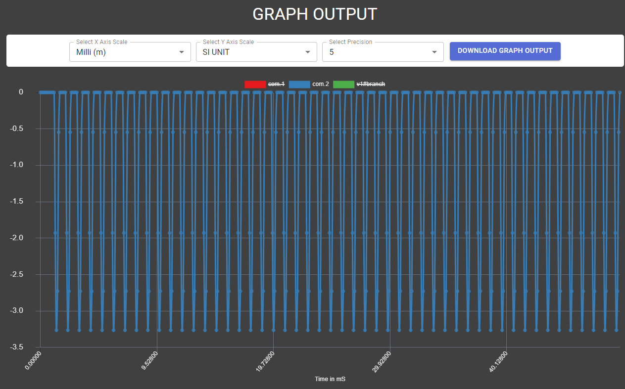
Conclusion:
We see an AC signal with a clipped positive part at the output thus ensuring Positive Clipping. Clippers have various applications like Voltage Protection, Wave Shaping, Signal Conditioning and Noise Reduction.
Assignment:
Design and implement a combination biased diode clipper capable of clipping at both sides at different voltage levels.
< Exp 5. BJT Inverter Switch up Exp 7. Diode Bridge Rectifier >